Iranian Classification Society Rules

< Previous | Contents | Next >
Section 7-2 Equipment for mooring at SPM
711. Application
1. The requirements in this Section apply to tests and inspections for the type approval of the equip- ment for mooring at SPM in accordance with the requirements of Pt 4, Ch 10, 101. 3. of the Rules.
2. The applicant of the type approval is not necessarily to be a manufacturer of the components, but to be those responsible for quality of the products.
3. The manufacturer who makes major components of the equipment for mooring at SPM shall obtain the Approval of Manufacturing Process of raw materials in accordance with the requirements in Pt 2, Ch. 1, 102 of the Rule.
712. Data to be submitted
The following reference data are to be submitted to the Society in addition to those specified in 102.
(1) Outline of manufacturing process of each major component
(2) General arrangement of the equipment for mooring at SPM and detailed assembly drawing of each component (materials of all components to be specified)
(3) Strength calculation sheets with 2 times the required safety factor
(4) Operation manual of the equipment for mooring at SPM
(5) Introduction of applicant and manufacturers of components
(6) Kind, mechanical properties and chemical composition of major materials for each component
(7) Method of heat treatment (if any required by the applied standard)
(8) Method of nondestructive test and list of qualified persons and qualification grade
(9) Data of quality control system of each component
713. Type tests
1. Test methods and acceptance criteria
(1) Components of equipment for mooring at SPM are to be assembled and fitted on the test unit according to the manufacturer's drawings. Tensile loads are to be applied with the proof test loads equivalent to the safe working load specified in Table 3.7.3 and following tensile test di- rection, and kept for at least 1 minute. Upon completion of type test, components of equipment for mooring at SPM are to have no permanent deformation.
(A) 90 degrees from the ship's centerline to port and starboard, and 30 degrees vertical wards
(B) 0 degrees sideway from the ship's centerline, and 30 degrees vertical downwards
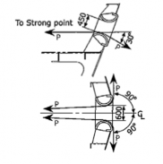
Fig 3.7.1 Tensile force directions
down-
Guidance for Approval of Manufacturing Process and Type Approval, Etc. 2015 79
![]()
Table 3.7.3 Safety working load
Deadweight (ton) | Safe working load(SWL) (ton) |
DWT ≤ 100,000 | 200 |
100,000 < DWT ≤ 150,000 | 250 |
150,000 < DWT | 350 |
(2) Chain stoppers and fairleads are to be wholly examined by ultrasonic test in principle, but,
if impracticable, test.
may be examined by effective non-destructive test such as magnetic particle
80 Guidance for Approval of Manufacturing Process and Type Approval, Etc. 2015
![]()